case study
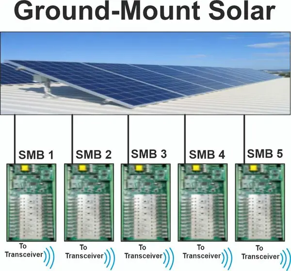
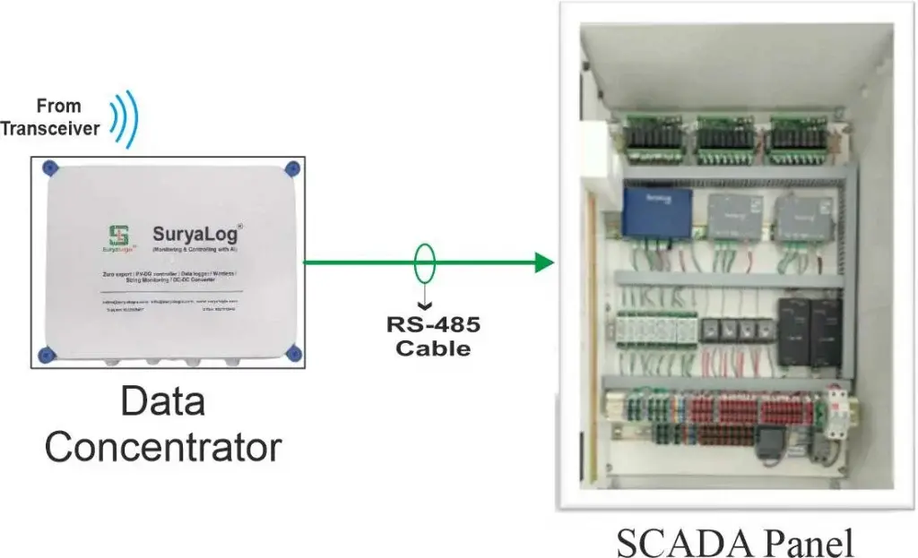
Ground Mount System
Rooftop System
String Monitoring Board
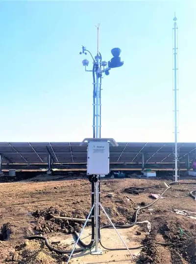
Sensor Pole
Ground Mount System
Challenges:
- Multiple ICR
- Cable can’t be lay
- Distance More Than 1 Km
- Multiple Inverter
- 207+ DI Configurable
- 30+ DO Configurable
Project details:
- No. of ICR: 2 No’s
- No. of Inverter: 5 No’s
- No. of Sensors: 5 No’s
Solution:
- As the distance is more communication of ICR to MCR was implemented through the OFC Communication Protocol.
- ICR-wise separate monitoring is available.
- As per the site scenario digital input card, and digital output cards are considered.
- Multiple types of output of the Sensor configuration with Weather Station having compatibility of connecting multiple types of Sensors.
Rooftop System
Challenges:
- Multiple Sources- Grid, DG, Gas Generator, Solar
- Synchronization of multiple type of Sources
- Multiple Inverter
- Multiple Grid incomer
- Multiple Wings
Project details:
- No. of Inverter: 10 No’s
- No. of ACDB: 3 No’s
- No of Grid Incomer: 2 No’s
- No. of DG: 2No’s and 1 Port for future
- No. of Gas Generator: 1 No’s
Solution:
- Hybrid Controller for Synchronization of multiple devices like Grid, DG, Gas Generator, Solar
- Looping of multiple Inverters through RS-485 cable.
- As the distance is 300 to 400-meter RS-485 Cable used was of the specifications- 2 pair, Screen-shielded Armored Cable
- Multiple Sense Cables are laid to understand which sources are turned ON.
- Remote & Local Monitoring.
String Monitoring Board
Challenges:
- To benefit the consumer by Monitoring the data of each String in the Ground Mount Plant.
- To get the Status of each String in the Plant.
Project details:
- After the installation of SuryaLogix SMB, the plant owner solved all the problems that were related to the Strings i.e. functioning or not, its status like BUS Voltage, SPD Status, Individual String Current, etc.
- It is used for continuously monitoring individual String Currents and Common Bus Voltage on a real-time basis with the Temperature Measurement facility for keeping a check on the Temperature inside the box.
Solution:
The plant owner is satisfied using the SuryaLogix SMB because the burden of physically checking every string periodically is reduced. Even instant trouble-shooting is possible resulting in reduced downtime.
Sensor Pole
Agenda:
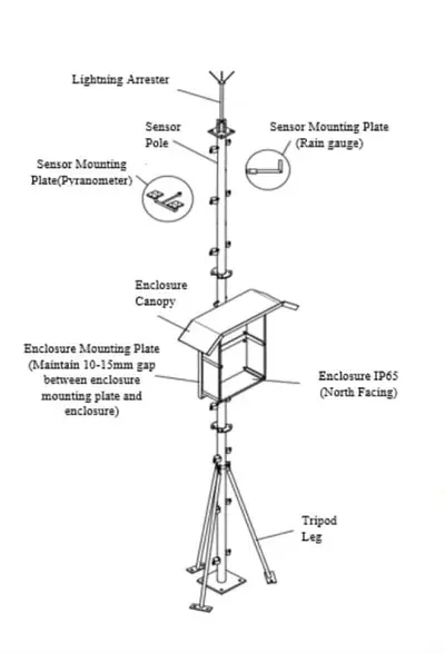
Providing proper Solution in order to protect the Device & Sensor from Surges.
Site Details:
Total No. of Sensors Installed: 12 No’s
Quantity:
- Irradiance Sensor/ Pyranometer: 4 No’s
- Module Temperature Sensor: 4 No’s
- Wind Speed & Direction Sensor: 1 No’s
- Humidity + Ambient Sensor: 1 No’s
- Rain Gauge Sensor: 1 No’s
- Lightning Arrestor: 1 No’s
Solution:
- Earth Resistance should be less than 1 ohm.
- Ensure that the Distance between electrodes and both earth pits should be more than 3 meters.
- Do not combine Lightning arrester and Communication /Pole Earthing.
- Connect Lightning arrester earthing cable to Earthing Pit 1 and Communication/Pole earthing to Earthing pit 2.
- Proper electrodes, plates, etc. with chemical Earthing should be used.
- Please keep Lightning Arrester, its cables, connections to the earth pit, etc. completely isolated and separate.


